


🎛️ Tune into Innovation with Every Wave!
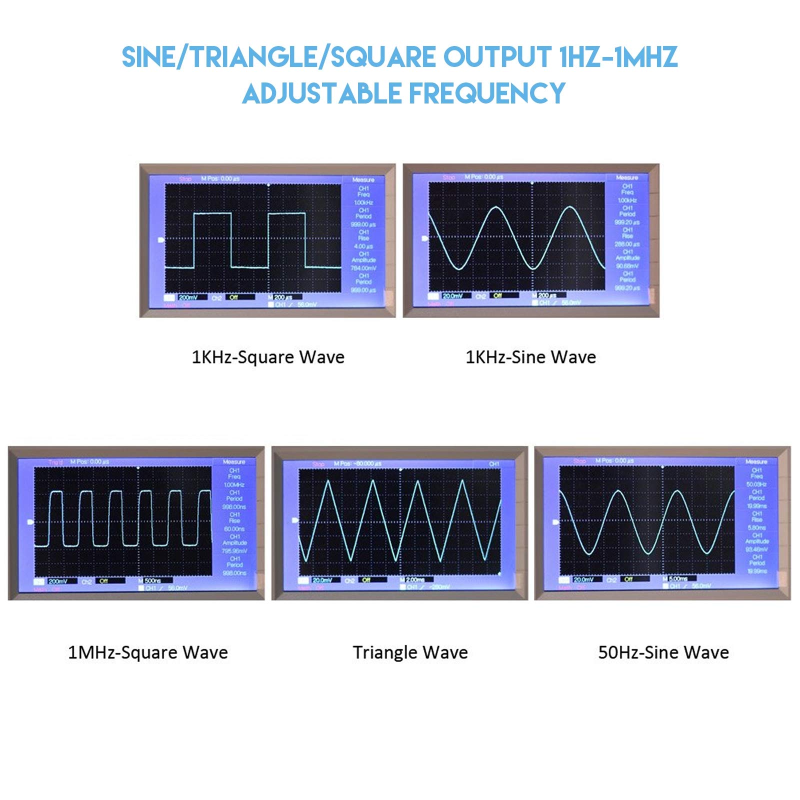
The XR2206 Precise Function Signal Generator Kit is a versatile DIY module that allows users to generate sine, triangle, and square waveforms with exceptional precision. Operating within a frequency range of 1Hz to 1MHz and powered by a 9-12V DC input, this kit is perfect for both professional engineers and hobbyists looking to explore the world of signal generation. With a transparent case for easy assembly and monitoring, it combines functionality with a sleek design.


S**A
Fine if you have a lower resistor for R4
Beware of the value of R4. That resistance controls the shape of the sine wave. 330 ohms is too high for my chip, so the sine wave was still too triangular. 220 ohms did better. If this is for having a second signal generator for breadboarding, you already have a breadboard, and should find an appropriate value for your chip, before soldering onto the pcb. I also skipped putting C8 in parallel with C7. C7 alone was fine enough for my needs.The value of C1 is depicted as 100uF, but tabulated as 47uF. The kit came with 47uF, and it's just a filtering cap, so it's fine.The XR2206CP itself comes off the pcb, so I can use it on a breadboard for other bands, pulses, ramps, fm, or am, as needed.Still five stars, despite the above caveats, because I have a breadboard, and a 220 ohm resistor to swap. Take away stars as needed if you don't.
R**S
Should I rate it one star or five stars - I'm torn
As others have noted, the assembly instructions for this kit leave more than a little bit to be desired, which warrants a single star. On the other hand, I did get it assembled (first try!) and it's a terrific little device for very little money which warrants 5 stars.I'm a hobbyist and not looking for great precision. I suspect that for other users the accuracy level of this device is insufficient.Now, to the problems with the instructions. The instructions packaged with the product were unreadable. It looks like what you get after a copy is made, then another copy from the first, then a third copy from the second, etc. My copy looks like its about the 50th copy and was unreadable with much of the text partially to completely faded out.But I found two other sellers of this same product on Amazon, and one of them had fairly decent photos of the instructions in their Amazon listing, so I downloaded those images and printed them.Even then, there were issues with gibberish and some totally incorrect information.Right of the bat you are told "The components are welding the front board ..." It's pretty easy to figure out that by "welding" they mean "soldered", but a novice to soldering devices onto boards would thing that the soldering must be done from the front.Another example, mounting instructions for the electrolytic capacitors say "The positive short feet negative long feet." The first problem is that this comes close to aforementioned gibberish, but the more significant problem is that the best interpretation would be that the short lead is the positive lead and that the long lead is the negative. Unfortunately, that is completely incorrect. The standard for these capacitors is the opposite - the short lead is the negative lead. Fortunately, these capacitors also had markings on them indicating which lead was the negative, confirming for me that the short lead was the negative.There is more negative/positive confusion. For the power supply there is the statement "inside outside is negative polarity". This was in the instructions I found online. That part of the instructions turned out to be legible in the instructions that came with the product and said unambiguously "center positive/barrel negative." So that's what I went with.There are many things left unsaid in the instructions, so for someone who has no experience with electronic components and soldering they are completely insufficient. For example, while you are warned that the IC must be properly inserted but they don't bother to mention that you do that by matching up the notch in the IC with the notch in the socket. Instead here is what the instructions say (I kid you not): "Pay attention to the direction of the IC, insert the might damage the chip!" and "check the IC whether against, such as anti please timely correction." Now that last bit of gibberish is completely undecipherable to me!The four screws that were in the kit for mounting the circuit board onto the bottom of the case were too short. I had to use my own M3 x 12 mm which worked perfectly. It also took a lot of fiddling to fit the top onto the case while getting each of the four sides to fit into their slots. Eventually it all came together, but it was a very frustrating 15 minutes.Then I powered it up and connected it to my scope and it was working perfectly! Got nice sine, square and triangular wave forms at varying frequencies. So that's left me with a nice feeling of accomplishment.Other reviews have said this as well. If you have some experience with electronic components and soldering, and don't need calibration level accuracy, this will probably work well for you. Otherwise, stay away.
N**E
Junk
This unit is poor quality. At least the one I received. Only has a sine wave. If I switch to square or triangle it stays sine. None off the knobs work. Waste of $10 dollars. Want my money back. Sold me $1 in parts for $9.99. Never again.
A**R
Fun to build, works, cheap signal generator
This is a great cheap little kit considering it includes a case and knobs.Tips:1. Check online for all sorts of tips2. Make sure all parts are soldered tight onto the board since the case holds the board in place by everything just fitting tightly. Example is IC socket as well as variable resistors.3. Two of the tall capacitors fit better if you lay them down on the board or else they can push on the case.4. I needed to just slightly file one of the case tabs so I did not need to force it in.5. If you have not build one of these inexpensive kits and their plexi case. Just be patient and enjoy the process. Example pealing paper of of the plexi does take time but will work.6. The 4 short screws are for alignment and spacing to the case bottom. You may need to slide them a little in their board holes, just loosen and re-tighten them, to get them to align with the holes in the case bottom.7. After soldering you need to trim all the parts such as caps and resistors but ALSO other parts such as the power connector. Put the bottom part of the case on, after inserting the 4 short screws and nuts, to see what all should be trimmed.PROS1. Cheap2. Works fine when built3. You get a nice little case and knobs4. Fun little projectCONS1. No real instructions at all. Just a faded circuit diagram and parts list. The diagram is correct and the circuit board is stenciled well so you can work this out without any help.2. Zero instructions on the case. As mentioned above the 4 small screws are attached to the circuit board via the 4 nuts and are use to align the board to the case and the nuts act as spacers. The long screws hold the case together without nuts, they just screw into holes in the case and work fine as such. Be careful since I same some builds online that skipped the 4 small screws.
Trustpilot
1 month ago
1 month ago


